Use StyleSelectors in an MVVM Diagramming Application
This article describes how to use StyleSelectors in an MVVM application to apply different styles on the RadDiagram shapes and connections based on business logic.
For the purpose of this tutorial, we will populate the RadDiagram control with three different node types and a custom link implementation.
Please note that the examples in this tutorial are showcasing Telerik Windows8 theme. In the Implicit Styles article you can find more information on how to set an application-wide theme.
Let's start by creating RectangleNode, EllipseNode and DecisionNode classes to describe the RadDiagramShapes:
public class EllipseNode : NodeViewModelBase
{
    public EllipseNodeType Type { get; set; }
}

public enum EllipseNodeType
{
    Start,
    End
}

public class RectangleNode : NodeViewModelBase
{
    public string Description { get; set; }
}

public class DecisionNode : NodeViewModelBase
{
    public string Content { get; set; }
}Imports Telerik.Windows.Controls.Diagrams.Extensions.ViewModels
Public Class EllipseNode
Inherits NodeViewModelBase
Public Property Type() As EllipseNodeType
End Class
Public Enum EllipseNodeType
Start
[End]
End Enum
Public Class RectangleNode
Inherits NodeViewModelBase
Public Property Description() As String
End Class
Public Class DecisionNode
Inherits NodeViewModelBase
Public Overloads Property Content() As String
End ClassPlease note that all three classes derive from the NodeViewModelBase class. You can find the implementation of this class in the Telerik.Windows.Controls.Diagrams.Extensions.ViewModels namespace as it is one of the ViewModels provided out-of-the-box in the Telerik.Windows.Controls.Diagrams.Extensions assembly.
Next, we need to define the ViewModel that will represent the RadDiagramConnections in our diagramming solution. For simplicity, we will create only one class but we will define a Type property to describe each link.
public class Link : LinkViewModelBase<NodeViewModelBase>
{
    public LinkType Type { get; set; }

    public Link()
        : base()
    { }

    public Link(NodeViewModelBase source, NodeViewModelBase target)
        : base(source, target)
    {
    }
}

public enum LinkType
{
    RightToLeft,
    LeftToRight,
    Normal
}Imports Telerik.Windows.Controls.Diagrams.Extensions.ViewModels
Public Class Link
Inherits LinkViewModelBase(Of NodeViewModelBase)
Public Property Type() As LinkType
Public Sub New()
MyBase.New()
End Sub
Public Sub New(ByVal source As NodeViewModelBase, ByVal target As NodeViewModelBase)
MyBase.New(source, target)
End Sub
End Class
Public Enum LinkType
RightToLeft
LeftToRight
Normal
End EnumPlease note that the Link class also derives from one of the ViewModels provided by the Diagramming Framework. The LinkViewModelBase
class implementation can be found in the Telerik.Windows.Controls.Diagrams.Extensions.ViewModels namespace in the Telerik.Windows.Controls.Diagrams.Extensions assembly.
Now that our items' ViewModels are defined, we have to create a collection of items to pass to the RadDiagram.GraphSource. Telerik Diagramming Framework provides a few built-in ViewModels that can be used out-of-the-box when creating a collection of diagramming items. You can examine the following list of tutorials to get a better understanding of the different scenarios and collections you can use in an MVVM diagramming solution:
In this example we will use the ObservableGraphSourceBase<TNode,TLink> class to create a custom GraphSource implementation as this will allow us to take advantage of the predefined AddNode(), AddLink(), CreateNode(), CreateLink(), RemoveNode() and RemoveLink() methods. This way we won't have to explicitly define a custom add/create/remove logic for our business items.
public class GraphSource : ObservableGraphSourceBase<NodeViewModelBase, Link>
{
}Public Class GraphSource
Inherits ObservableGraphSourceBase(Of NodeViewModelBase, Link)
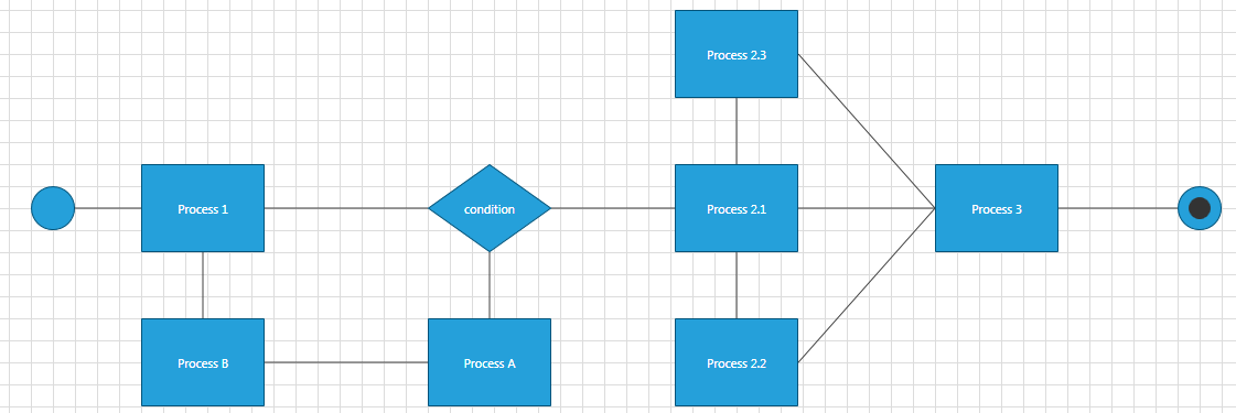
End Class Let's define the items in the GraphSource to describe the following process workflow:
public class GraphSource : ObservableGraphSourceBase<NodeViewModelBase, Link>
{
    public void PopulateGraphSource()
    {
        //Add Nodes
        RectangleNode processNode1 = new RectangleNode()
        {
            Position = new Point(160, 280),
            Description = "Process 1"
        };
        this.AddNode(processNode1);
        RectangleNode processNode2 = new RectangleNode()
        {
            Position = new Point(644, 280),
            Description = "Process 2.1"
        };
        this.AddNode(processNode2);
        RectangleNode processNode3 = new RectangleNode()
        {
            Position = new Point(644, 420),
            Description = "Process 2.2"
        };
        this.AddNode(processNode3);
        RectangleNode processNode4 = new RectangleNode()
        {
            Position = new Point(644, 140),
            Description = "Process 2.3"
        };
        this.AddNode(processNode4);
        RectangleNode processNode5 = new RectangleNode()
        {
            Position = new Point(880, 280),
            Description = "Process 3"
        };
        this.AddNode(processNode5);
        RectangleNode processNode6 = new RectangleNode()
        {
            Position = new Point(420, 420),
            Description = "Process A"
        };
        this.AddNode(processNode6);
        RectangleNode processNode7 = new RectangleNode()
        {
            Position = new Point(160, 420),
            Description = "Process B"
        };
        this.AddNode(processNode7);

        DecisionNode decisionNode = new DecisionNode()
        {
            Position = new Point(420, 280),
            Content = "condition"
        };
        this.AddNode(decisionNode);
        EllipseNode endNode = new EllipseNode()
        {
            Position = new Point(1100, 300),
            Type = EllipseNodeType.End
        };
        this.AddNode(endNode);
        EllipseNode startNode = new EllipseNode()
        {
            Position = new Point(60, 300),
            Type = EllipseNodeType.Start,
            Content = "Start"
        };
        this.AddNode(startNode);

        //Add Links
        this.AddLink(new Link(startNode, processNode1) { Type = LinkType.LeftToRight });
        this.AddLink(new Link(processNode1, decisionNode) { Type = LinkType.LeftToRight });
        this.AddLink(new Link(decisionNode, processNode2) { Type = LinkType.LeftToRight });
        this.AddLink(new Link(processNode2, processNode3) { Type = LinkType.Normal });
        this.AddLink(new Link(processNode2, processNode4) { Type = LinkType.Normal });
        this.AddLink(new Link(processNode2, processNode5) { Type = LinkType.LeftToRight });
        this.AddLink(new Link(processNode3, processNode5) { Type = LinkType.LeftToRight });
        this.AddLink(new Link(processNode4, processNode5) { Type = LinkType.LeftToRight });
        this.AddLink(new Link(processNode5, endNode) { Type = LinkType.LeftToRight });
        this.AddLink(new Link(processNode6, decisionNode) { Type = LinkType.RightToLeft });
        this.AddLink(new Link(processNode7, processNode6) { Type = LinkType.RightToLeft });
        this.AddLink(new Link(processNode1, processNode7) { Type = LinkType.RightToLeft });
    }
}Public Class GraphSource
Inherits ObservableGraphSourceBase(Of NodeViewModelBase, Link)
Public Sub PopulateGraphSource()
'Add Nodes'
Dim processNode1 As New RectangleNode() With {.Position = New Point(160, 280), .Description = "Process 1"}
Me.AddNode(processNode1)
Dim processNode2 As New RectangleNode() With {.Position = New Point(644, 280), .Description = "Process 2.1"}
Me.AddNode(processNode2)
Dim processNode3 As New RectangleNode() With {.Position = New Point(644, 420), .Description = "Process 2.2"}
Me.AddNode(processNode3)
Dim processNode4 As New RectangleNode() With {.Position = New Point(644, 140), .Description = "Process 2.3"}
Me.AddNode(processNode4)
Dim processNode5 As New RectangleNode() With {.Position = New Point(880, 280), .Description = "Process 3"}
Me.AddNode(processNode5)
Dim processNode6 As New RectangleNode() With {.Position = New Point(420, 420), .Description = "Process A"}
Me.AddNode(processNode6)
Dim processNode7 As New RectangleNode() With {.Position = New Point(160, 420), .Description = "Process B"}
Me.AddNode(processNode7)
Dim decisionNode_Renamed As New DecisionNode() With {.Position = New Point(420, 280), .Content = "condition"}
Me.AddNode(decisionNode_Renamed)
Dim endNode As New EllipseNode() With {.Position = New Point(1100, 300), .Type = EllipseNodeType.End}
Me.AddNode(endNode)
Dim startNode As New EllipseNode() With {.Position = New Point(60, 300), .Type = EllipseNodeType.Start, .Content = "Start"}
Me.AddNode(startNode)
'Add Links'
Me.AddLink(New Link(startNode, processNode1) With {.Type = LinkType.LeftToRight})
Me.AddLink(New Link(processNode1, decisionNode_Renamed) With {.Type = LinkType.LeftToRight})
Me.AddLink(New Link(decisionNode_Renamed, processNode2) With {.Type = LinkType.LeftToRight})
Me.AddLink(New Link(processNode2, processNode3) With {.Type = LinkType.Normal})
Me.AddLink(New Link(processNode2, processNode4) With {.Type = LinkType.Normal})
Me.AddLink(New Link(processNode2, processNode5) With {.Type = LinkType.LeftToRight})
Me.AddLink(New Link(processNode3, processNode5) With {.Type = LinkType.LeftToRight})
Me.AddLink(New Link(processNode4, processNode5) With {.Type = LinkType.LeftToRight})
Me.AddLink(New Link(processNode5, endNode) With {.Type = LinkType.LeftToRight})
Me.AddLink(New Link(processNode6, decisionNode_Renamed) With {.Type = LinkType.RightToLeft})
Me.AddLink(New Link(processNode7, processNode6) With {.Type = LinkType.RightToLeft})
Me.AddLink(New Link(processNode1, processNode7) With {.Type = LinkType.RightToLeft})
End Sub
End ClassNow we can set-up our RadDiagram control to display these items. For that purpose we can define a RadDiagram instance in our view and set its GraphSource property in the code-behind file:
<Grid>
    <telerik:RadDiagram x:Name="xDiagram" />
</Grid>public void SetDiagramSource()
{
GraphSource DiagramSource = new GraphSource();
DiagramSource.PopulateGraphSource();
this.xDiagram.GraphSource = DiagramSource;
}Partial Public Class MainWindow
Inherits Window
Public Sub New()
InitializeComponent()
Dim DiagramSource As New GraphSource()
DiagramSource.PopulateGraphSource()
Me.xDiagram.GraphSource = DiagramSource
End Sub
End ClassThis operation will place all DiagramItems at a position of (0,0) on top of each other. This is why we will need to apply a custom style to bind the Position of the items to the business values we defined in the GraphSource collection. However, as our process workflow uses different types of shapes, we will have to apply different styles for each node type. This is where we can take advantage of the RadDiagram.ShapeStyleSelector property and create a custom StyleSelector for our nodes.
As our example defines three different business nodes, we can create a StyleSelector that applies a style based on the type of the business class. Moreover, as the EllipseNode class exposes a Type property, we can also use its value to apply different styles for the start and end points of our process workflow.
public class NodeStyleSelector : StyleSelector
{
    public Style DecisionNodeStyle { get; set; }
    public Style StartNodeStyle { get; set; }
    public Style EndNodeStyle { get; set; }
    public Style RectangleNodeStyle { get; set; }

    public override Style SelectStyle(object item, DependencyObject container)
    {
        if (item is DecisionNode)
            return DecisionNodeStyle;
        else if (item is RectangleNode)
            return RectangleNodeStyle;
        else if (item is EllipseNode)
        {
            switch (((EllipseNode)item).Type)
            {
                case EllipseNodeType.Start:
                    return StartNodeStyle;
                case EllipseNodeType.End:
                    return EndNodeStyle;
                default:
                    return base.SelectStyle(item, container);
            }
        }
        else return base.SelectStyle(item, container);
    }
}Public Class NodeStyleSelector
Inherits StyleSelector
Public Property DecisionNodeStyle() As Style
Public Property StartNodeStyle() As Style
Public Property EndNodeStyle() As Style
Public Property RectangleNodeStyle() As Style
Public Overrides Function SelectStyle(ByVal item As Object, ByVal container As DependencyObject) As Style
If TypeOf item Is DecisionNode Then
Return DecisionNodeStyle
ElseIf TypeOf item Is RectangleNode Then
Return RectangleNodeStyle
ElseIf TypeOf item Is EllipseNode Then
Select Case (CType(item, EllipseNode)).Type
Case EllipseNodeType.Start
Return StartNodeStyle
Case EllipseNodeType.End
Return EndNodeStyle
Case Else
Return MyBase.SelectStyle(item, container)
End Select
Else
Return MyBase.SelectStyle(item, container)
End If
End Function
End ClassNow, let's declare this selector in the resources of our view and prepare the custom styles for each node type:
<Grid>
    <Grid.Resources>
        <Style x:Key="DecisionShapeStyle" TargetType="telerik:RadDiagramShape">
            <Setter Property="Position" Value="{Binding Position}" />
            <Setter Property="Height" Value="80" />
            <Setter Property="Geometry" Value="{telerik:FlowChartShape ShapeType=DecisionShape}" />
            <Setter Property="ContentTemplate">
                <Setter.Value>
                    <DataTemplate>
                        <TextBlock Text="{Binding Content}" />
                    </DataTemplate>
                </Setter.Value>
            </Setter>
        </Style>
        <Style x:Key="RectangleShapeStyle" TargetType="telerik:RadDiagramShape">
            <Setter Property="Position" Value="{Binding Position}" />
            <Setter Property="Height" Value="80" />
            <Setter Property="Geometry" Value="{telerik:CommonShape ShapeType=RectangleShape}" />
            <Setter Property="ContentTemplate">
                <Setter.Value>
                    <DataTemplate>
                        <TextBlock Text="{Binding Description}" />
                    </DataTemplate>
                </Setter.Value>
            </Setter>
        </Style>
        <Style x:Key="StartShapeStyle" TargetType="telerik:RadDiagramShape">
            <Setter Property="Position" Value="{Binding Position}" />
            <Setter Property="Width" Value="40" />
            <Setter Property="Height" Value="40" />
            <Setter Property="Geometry" Value="{telerik:CommonShape ShapeType=EllipseShape}" />
            <Setter Property="ContentTemplate">
                <Setter.Value>
                    <DataTemplate>
                        <Grid />
                    </DataTemplate>
                </Setter.Value>
            </Setter>
        </Style>
        <Style x:Key="EndShapeStyle" TargetType="telerik:RadDiagramShape">
            <Setter Property="Position" Value="{Binding Position}" />
            <Setter Property="Width" Value="40" />
            <Setter Property="Height" Value="40" />
            <Setter Property="Geometry" Value="{telerik:CommonShape ShapeType=EllipseShape}" />
            <Setter Property="ContentTemplate">
                <Setter.Value>
                    <DataTemplate>
                        <Ellipse Width="20" Height="20" Fill="#FF333333" />
                    </DataTemplate>
                </Setter.Value>
            </Setter>
        </Style>
        <styleselectors:NodeStyleSelector x:Key="CustomShapeStyleSelector"
                DecisionNodeStyle="{StaticResource DecisionShapeStyle}"
                EndNodeStyle="{StaticResource EndShapeStyle}"
                RectangleNodeStyle="{StaticResource RectangleShapeStyle}"
                StartNodeStyle="{StaticResource StartShapeStyle}" />
    </Grid.Resources>
    <telerik:RadDiagram
            ShapeStyleSelector="{StaticResource CustomShapeStyleSelector}"/>
</Grid>
If we run the solution at this point, we should get the following result: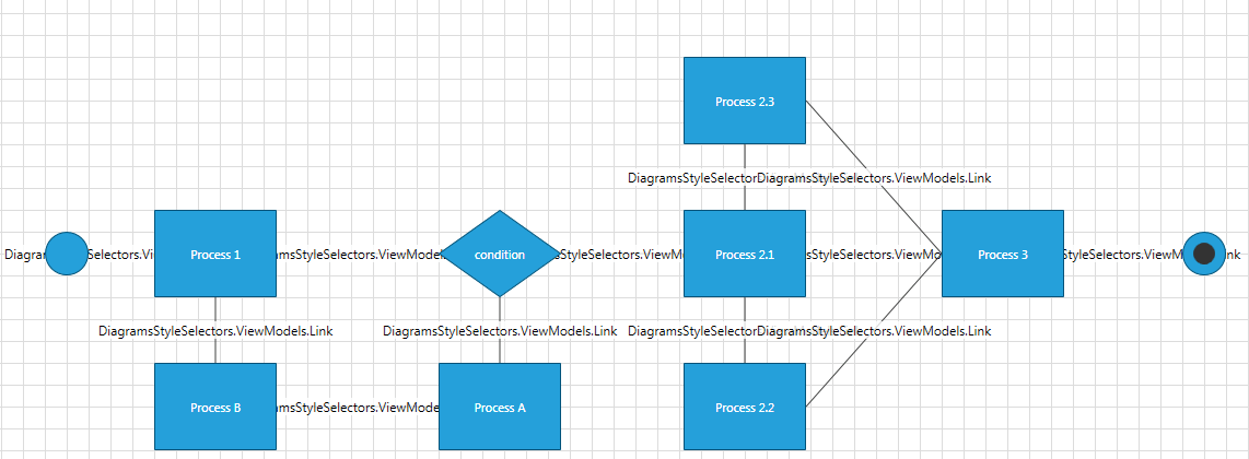
Now the RadDiagramShapes are properly styled and arranged, but the connections don't look all that good. This is due to the fact that they try to display their content and as we haven't declared a ConnectionTemplate, the Link class ToSting() method is used to display it. In this example we won't need to visualize any labels or descriptions near the connections, so we can define an empty Grid as a ContentTemplate of each RadDiagramConnection. Also, as we created a Type property in the Link class implementation and we added different types of links in the GraphSource collection, we can apply different styles for the connections based on their type. For that purpose, we will need another custom StyleSelector - this time we will use it with the RadDiagram.ConnectionStyleSelector property.
public class LinkStyleSelector : StyleSelector
{
    public Style NormalLinkStyle { get; set; }
    public Style RightCapLinkStyle { get; set; }
    public Style LeftCapLinkStyle { get; set; }

    public override Style SelectStyle(object item, DependencyObject container)
    {
        Link link = item as Link;
        if (link == null)
            return base.SelectStyle(item, container);
        else switch (link.Type)
            {
                case LinkType.RightToLeft:
                    return LeftCapLinkStyle;
                case LinkType.LeftToRight:
                    return RightCapLinkStyle;
                case LinkType.Normal:
                    return NormalLinkStyle;
                default:
                    return base.SelectStyle(item, container);
            }
    }
}Public Class LinkStyleSelector
Inherits StyleSelector
Public Property NormalLinkStyle() As Style
Public Property RightCapLinkStyle() As Style
Public Property LeftCapLinkStyle() As Style
Public Overrides Function SelectStyle(ByVal item As Object, ByVal container As DependencyObject) As Style
Dim link_Renamed As Link = TryCast(item, Link)
If link_Renamed Is Nothing Then
Return MyBase.SelectStyle(item, container)
Else
Select Case link_Renamed.Type
Case LinkType.RightToLeft
Return LeftCapLinkStyle
Case LinkType.LeftToRight
Return RightCapLinkStyle
Case LinkType.Normal
Return NormalLinkStyle
Case Else
Return MyBase.SelectStyle(item, container)
End Select
End If
End Function
End ClassAnd finally we need to define the connection styles and the LinkStyleSelector in the resources of our view:
<Grid>
    <Grid.Resources>
        <Style TargetType="telerik:RadDiagramConnection" x:Key="NormalConnectionStyle">
            <Setter Property="Stroke" Value="Brown" />
            <Setter Property="StrokeThickness" Value="2" />
            <Setter Property="StrokeDashArray" Value="2 2" />
            <Setter Property="ContentTemplate">
                <Setter.Value>
                    <DataTemplate>
                        <Grid />
                    </DataTemplate>
                </Setter.Value>
            </Setter>
        </Style>
        <Style TargetType="telerik:RadDiagramConnection" x:Key="TargetCapConnectionStyle">
            <Setter Property="TargetCapType" Value="Arrow1Filled" />
            <Setter Property="ContentTemplate">
                <Setter.Value>
                    <DataTemplate>
                        <Grid />
                    </DataTemplate>
                </Setter.Value>
            </Setter>
        </Style>
        <Style TargetType="telerik:RadDiagramConnection" x:Key="SourceCapConnectionStyle">
            <Setter Property="Stroke" Value="Red" />
            <Setter Property="SourceCapType" Value="Arrow1Filled" />
            <Setter Property="ContentTemplate">
                <Setter.Value>
                    <DataTemplate>
                        <Grid />
                    </DataTemplate>
                </Setter.Value>
            </Setter>
        </Style>
        <styleselectors:LinkStyleSelector x:Key="CustomConnectionStyleSelector"
				NormalLinkStyle="{StaticResource NormalConnectionStyle}"
				RightCapLinkStyle="{StaticResource TargetCapConnectionStyle}"
				LeftCapLinkStyle="{StaticResource SourceCapConnectionStyle}" />

    </Grid.Resources>
    <telerik:RadDiagram ConnectionStyleSelector="{StaticResource CustomConnectionStyleSelector}"
			ShapeStyleSelector="{StaticResource CustomShapeStyleSelector}"/>
</Grid>
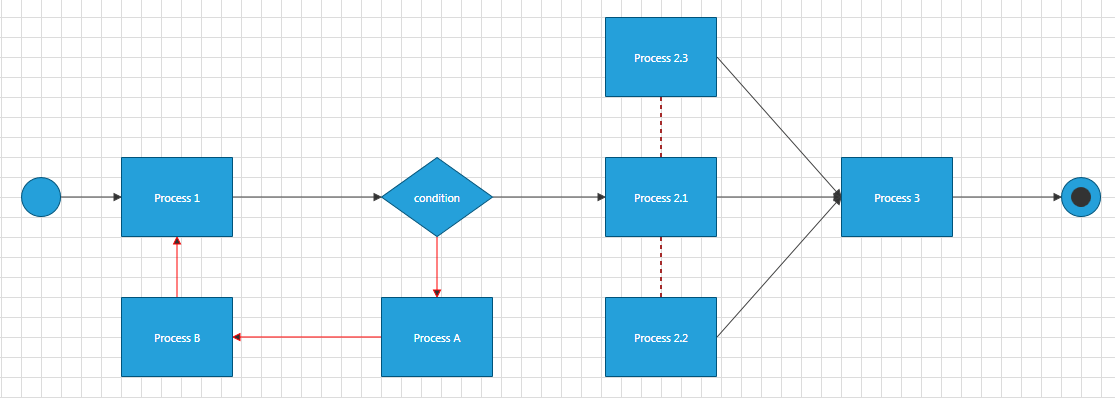
The final result of the solution we build should look like this: