Layout
configurationThe layout of a diagram consists in arranging the shapes (sometimes also the connections) in some fashion in order to achieve an aesthetically pleasing experience to the user. It aims at giving a more direct insight in the information contained within the diagram and its relational structure.
On a technical level, layout consists of a multitude of algorithms and optimizations:
- analysis of the relational structure (loops, multi-edge occurrence...)
- connectedness of the diagram and the splitting into disconnected components
- crossings of connections
- bends and length of links
and various ad-hoc calculations which depend on the type of layout. The criteria on which an algorithm is based vary but the common denominator is:
- a clean separation of connected components (subgraphs)
- an orderly organization of the shapes in such a way that siblings are close to another, i.e. a tight packing of shapes which belong together (parent of child relationship)
- a minimum of connection crossings
Kendo diagram includes three of the most used layout algorithms which should cover most of your layout needs - tree layout, force-directed layout and layered layout. Please, check the type property for more details regarding each type.
layout
Objectlayout.endRadialAngle
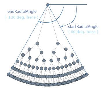
NumberDefines where the circle/arc ends. The positive direction is clockwise and the angle is in degrees. This setting is specific to the radial tree layout.
Default: 360
layout.grid
ObjectEach layout algorithm has a different set of parameters customizing the layout but they also all have a common collection of parameters which relate to the way 'pieces' of a diagram are organized.
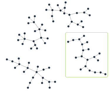
A diagram can have in general disconnected pieces, known as components, which can be organized in a way independent of the way a component on its own is arranged. In the picture above, this is one diagram consisting of four components.
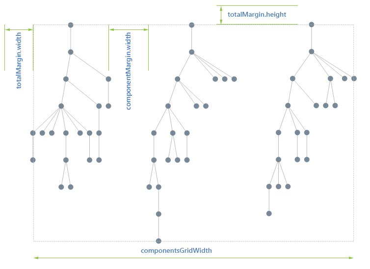
When you apply a certain layout an analysis will first split the diagram in components, arrange each component individually and thereafter organize the components in a grid. The common parameters referred above deal with this grid layout, they define the width, margin and padding of the (invisible) grid used to organize the components.
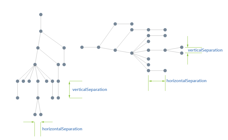
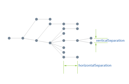
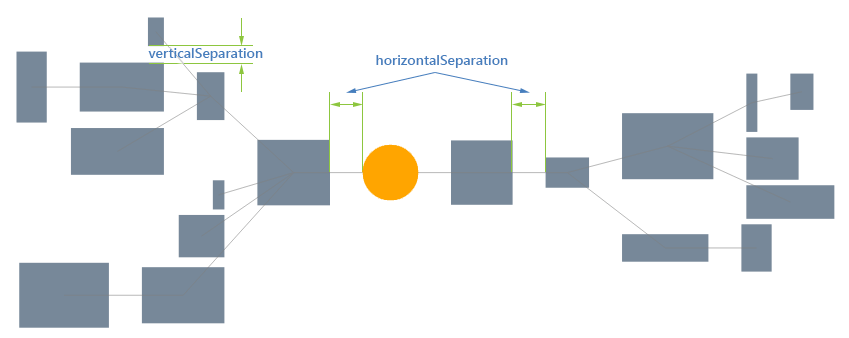
Either the distance between the siblings if the tree is up/down or between levels if the tree is left/right. In tipOver tree layout this setting is used only for the direct children of the root
Default: 90
layout.iterations
NumberThe number of times that all the forces in the diagram are being calculated and balanced. The default is set at 300, which should be enough for diagrams up to a hundred nodes. By increasing this parameter you increase the correctness of the simulation but it does not always lead to a more stable topology. In some situations a diagram simply does not have a stable minimum energy state and oscillates (globally or locally) between the minima. In such a situation increasing the iterations will not result in a better topology.
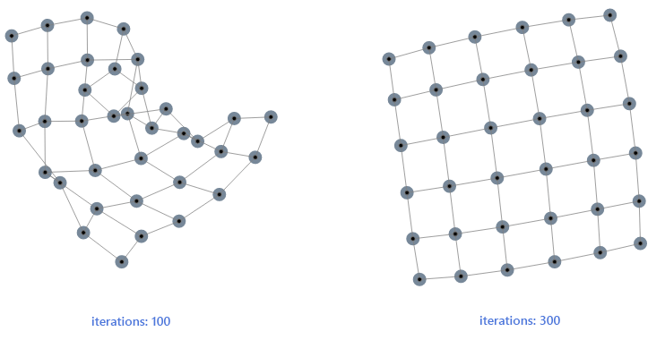
In situations where there is enough symmetry in the diagram the increased number of iterations does lead to a better layout. In the example below the 100 iterations was not enough to bring the grid to a stable state while 300 iterations did bring all the nodes in such a position that the (virtual) energy of the diagram is a minimum.
This setting is specific to the force-directed layout
Default: 300
layout.layerSeparation
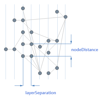
NumberThe height (in a vertical layout) or width (in a horizontal layout) between the layers.
Default: 50
layout.nodeDistance
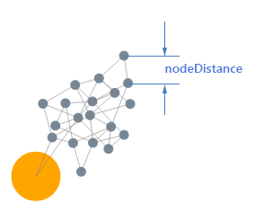
NumberIn the force-directed layout this setting defines the optimal length between 2 nodes, which directly correlates to the state of the link between them. If a link is longer than there will be a force pulling the nodes together, if the link is shorter the force will push the nodes apart. The optimal length is more and indication in the algorithm than a guarantee that all nodes will be at this distance. The result of the layout is really a combination of the incidence structure of the diagram, the initial topology (positions of the nodes) and the number of iterations.
In the layered layout it defines the minimum distance between nodes on the same level. Due to the nature of the algorithm this distance will only be respected if the whole crossing of links and optimization does not induce a shift of the siblings.
This setting is specific to the force-directed layout and layered layout
Default: 50
Controls the distance between the root and the immediate children of the root. This setting is specific to the radial tree layout.
Default: 200
layout.radialSeparation
NumberDefines the radial separation between the levels (except the first one which is defined by the aforementioned radialFirstLevelSeparation). This setting is specific to the radial tree layout.
Default: 150
layout.startRadialAngle
NumberDefines where the circle/arc starts. The positive direction is clockwise and the angle is in degrees. This setting is specific to the radial tree layout.
Default: 0
layout.subtype
StringThe subtype further defines the layout type by specifying in greater detail the behaviour expected by the layout algorithm. Possible predefined values are:
-
"down" - tree layout and layered layout specific subtype. In the tree layout the root is arranged at the top and its children downwards. For the layered layout the links are directed downwards. This is the default subtype.

-
"up" - tree layout and layered layout specific subtype. In the tree layout the root is arranged at the bottom and its children upwards. For the layered layout the links are directed upwards.
-
"left" - tree layout layered layout specific subtype. In the tree layout the root is arranged at the left and its children sideways to the right. For the layered layout the links are directed to the left.
-
"right" - tree layout layered layout specific subtype. In the tree layout the root is arranged at the right and its children sideways to the left. For the layered layout the links are directed downwards.
-
"mindmapHorizontal" - tree layout specific subtype. The root sits at the center and its children are spread equally to the left and right.
-
"mindmapVertical" - tree layout specific subtype. The root sits at the center and its children are spread equally above and below.
-
"radial" - tree layout specific subtype. The root sits at the center and its children are spread radially around.
Default: "down"
<div id="diagram"></div>
<script>
$("#diagram").kendoDiagram({
    shapes: [
        { id: "1", x: 100, y: 250, content: { text: "Root" } },
        { id: "2", x: 200, y: 150, content: { text: "Child 1" } },
        { id: "3", x: 200, y: 350, content: { text: "Child 2" } }
    ],
    connections: [
        { from: "1", to: "2" },
        { from: "1", to: "3" }
    ],
    layout: {
        type: "tree",
        subtype: "right"
    }
});
</script>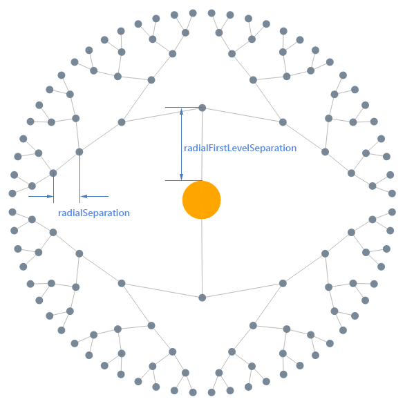
-
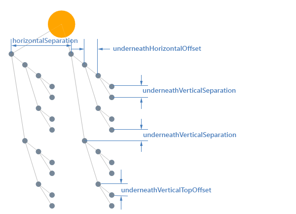
"tipOver" - tree layout specific subtype. A special version of the tree-down layout where the grand-children (and iteratively) are arranged vertically while the direct children are arranged horizontally. This arrangement has the advantage that it doesn't spread as much as the classic tree-down layout. See below for a concrete example.
-
"horizontal" - layered layout specific subtype. The preferred direction of the links is horizontal.
-
"vertical" - layered layout specific subtype. The preferred direction of the links is vertical.
Specifies the start level when the subtype is tipOver.
Default: 0
layout.type
StringThe type of the layout algorithm to use. Predefined values are:
-
"tree" - Organizes a diagram in a hierarchical way and is typically used in organizational representations. This type includes the radial tree layout, mindmapping and the classic tree diagrams.
-
"force" - Force-directed layout algorithm (also known as the spring-embedder algorithm) is based on a physical simulation of forces acting on the nodes whereby the links define whether two nodes act upon each other. Each link effectively is like a spring embedded in the diagram. The simulation attempts to find a minimum energy state in such a way that the springs are in their base-state and thus do not pull or push any (linked) node. This force-directed layout is non-deterministic; each layout pass will result in an unpredictable (and hence not reproducible) layout. The optimal length is more and indication in the algorithm than a guarantee that all nodes will be at this distance. The result of the layout is really a combination of the incidence structure of the diagram, the initial topology (positions of the nodes) and the number of iterations.
-
"layered" - Organizes the diagram with an emphasis on flow and minimizing the crossing between layers of shapes. This layout works well when few components are present and some sort of top-down flow is present. The concept of flow in this context being a more or less clear direction of the connections with a minimum of cycles (connections flowing back upstream). Layered graph layout is a type of graph layout in which the nodes of a (directed) graph are drawn in horizontal or vertical layers with the links directed in the complementary direction. It is also known as Sugiyama or hierarchical graph layout. When the graph is a tree the layout reduces to a standard tree layout and thus can be considered as an extension to the classic tree layout.
There are several criteria on which this algorithm is based and which are respected in as far as the incidence structure allows it:
- links have a preferred direction (the complementary direction of the subtype) and attempt to flow as much as possible in this way
- linked nodes try to stay closed to one another (clustering of nodes)
- links crossings should be minimized
- links should be as short as possible (cross a few layers as possible)
The construction of a layered graph drawing proceeds in a series of steps (assuming an horizontal layer from here on):
- If the input graph is not already a directed acyclic graph, a set of edges is identified the reversal of which will make it acyclic.
- The nodes of the directed acyclic graph resulting from the first step are assigned to layers, such that each link goes from a higher layer to a lower layer.
- Edges that span multiple layers are replaced by paths of dummy vertices so that, after this step, each edge in the expanded graph connects two vertices on adjacent layers of the drawing.
- The nodes within each layer are permuted in an attempt to reduce the number of crossings among the edges connecting it to the previous layer.
- Each node is assigned a coordinate within its layer, consistent with the permutation calculated in the previous step.
- The edges reversed in the first step of the algorithm are returned to their original orientations, the dummy vertices are removed from the graph and the vertices and edges are drawn.
Default: "tree"
Defines the horizontal offset from a child with respect to its parent. This setting is specific to the tipOver tree layout.
Default: 15
Defines the vertical separation between siblings and sub-branches. This setting is specific to the tipOver tree layout.
Default: 15
Defines the vertical separation between a parent and its first child. This offsets the whole set of children with respect to its parent. This setting is specific to the tipOver tree layout.
Default: 15
Either the distance between levels if the tree is up/down or between siblings if the tree is left/right. This property is not used in tipOver tree layout but rather replaced with three additional ones - underneathVerticalTopOffset, underneathVerticalSeparation and underneathHorizontalOffset
Default: 50