Hi,
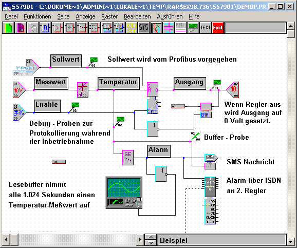
I have been given the task of rewriting an old application, and I'd like to use the RadControls for some parts of it. In this application, the user has to be able to place items on a schematic view, like this.
I have a couple of questions though, because I wasn't able to figure out how to do the following things from the RadDiagram Help/Tutorials, as I am quite new to more advanced WPF stuff (have only written relatively simple apps before) and MVVM in general:
1. How can I create diagram objects (for starters, they can just be rectangles) that simply have an Image control with their respective Bitmap set as the source (so I can get objects like in the screenshot by using the bitmaps that I have and avoid having to write their Geometry in WPF), with multiple connectors on each side (like the ISDN block in the lower right corner), and a Dictionary for each instance of an object to store custom properties? I've been through the "How To Create Custom Shape" tutorial, but still don't really know how to tackle this problem.
2. How do I add these objects to the toolbox later on? Do I just create a Gallery (ObservableCollection) with those Shapes and add that to the item ObservableCollection of my ViewModel?
Thanks
5 Answers, 1 is accepted
0

Hello Vladimir,
I prepared a sample solution that demonstrates how to implement the described requirements.
I chose an MVVM approach where the RadDiagram.GraphSource is bound to a collection of business items. With this approach you can associate each RadDiagramItem (Shape or Connection) with a business object and keep additional data for them.
Also, I defined an Image control in the ContentTemplate of the RadDiagramShapes and bound its Source to a business property that keeps the url to the image that has to be displayed inside each shape. And I also added a TextBlock to display a string value in case there is no image source for a shape.
And as you said you need to display the shapes connectors, I edited the default ControlTemplate of the RadDiagramShape. By default the connectors of each shape are displayed only when they are activated while a connection is build. And if you want to display the connectors at all times, you need to set a Visible Visibility to the ConnectorsControl element of the RadDiagramShape.Template.
Please note that the RadDiagram control exposes ShapeStyle and ShapeStyleSelector properties. This means that you can create custom logic and determine the style of each shape on that logic. This will allow you to create custom ControlTemplates only on certain shapes thus displaying the ConnectorsControl only on some shapes.
And in order to create custom connectors, you can take a look at this article. Basically, you'll need to create the connectors from code-behind and you may need to remove the default connectors beforehand (depending on your requirements). Also, as the default connector's style is in the form of an ellipse, you might want to change its style as well as demonstrated in the attached sample.
Finally, you can use the ViewModels that describe the DiagramItems to populate the RadDiagramToolBox with items. If you go with that approach, please take a closer look at the drag/drop implementation in the sample solution and let me know if you have any question.
Regards,
Tina Stancheva
the Telerik team
Explore the entire Telerik portfolio by downloading Telerik DevCraft Ultimate.
0

Vladimir
Top achievements
 Rank 1
answered on 02 Jan 2013, 03:00 PM
Hi Tina,
Thanks for your answer. The sample solution that you attached already helped me a lot in understanding how the RadDiagram works, and I defined a few diagram shapes (blocks) in a ResourceDictionary, like this:
ConnectorList is simply a class defined as
However, I still have some questions pertaining to the diagram, some also related to the GraphSource class, the way I can keep additional information on objects and show that information in a RadPropertyGrid:
1. I would like to be able to define properties for each type of block which I can then show and edit in a RadPropertyGrid. It would be ideal if they could be defined in the XAML in a Dictionary<string, object> for each type of block, and this dictionary would then be kept as an instance property for each block on the diagram. I am unclear, however, how to do this in particular; I managed to define the PropertyDefinitions in the code-behind, but would like to avoid this as much as possible.
2. Is it possible to change the behavior of the RadDiagram in such a way that connections between two points are not just straight connections from one point to another, but that the user can only lay out the connections along the grid (and that turns can only be at 90 degree angles, as can be seen in the screenshot)? I was thinking of using the ConnectionManipulationCompleted event and creating an infinitely small dummy shape with just one connector in its middle in order to allow the user to make "turns" himself, but maybe there is a better way? This approach would probably also work better in order to be able to connect multiple wires to each other, but again, I don't want to reinvent the wheel if there is another option.
Regards
Thanks for your answer. The sample solution that you attached already helped me a lot in understanding how the RadDiagram works, and I defined a few diagram shapes (blocks) in a ResourceDictionary, like this:
<viewModels:NodeViewModel x:Name="FncNand" Title="FncNand" Id="52" ImageSource="Images/Blocks/Digital/fncnand.bmp"> <viewModels:NodeViewModel.Connectors> <local:ConnectorList> <Point x:Key="DI_0" X="0" Y="0.25"/> <Point x:Key="DI_1" X="0" Y="0.75"/> <Point x:Key="DO_0" X="1" Y="0.5"/> </local:ConnectorList> </viewModels:NodeViewModel.Connectors></viewModels:NodeViewModel>ConnectorList is simply a class defined as
public class ConnectorList : Dictionary<string, Point> {}However, I still have some questions pertaining to the diagram, some also related to the GraphSource class, the way I can keep additional information on objects and show that information in a RadPropertyGrid:
1. I would like to be able to define properties for each type of block which I can then show and edit in a RadPropertyGrid. It would be ideal if they could be defined in the XAML in a Dictionary<string, object> for each type of block, and this dictionary would then be kept as an instance property for each block on the diagram. I am unclear, however, how to do this in particular; I managed to define the PropertyDefinitions in the code-behind, but would like to avoid this as much as possible.
2. Is it possible to change the behavior of the RadDiagram in such a way that connections between two points are not just straight connections from one point to another, but that the user can only lay out the connections along the grid (and that turns can only be at 90 degree angles, as can be seen in the screenshot)? I was thinking of using the ConnectionManipulationCompleted event and creating an infinitely small dummy shape with just one connector in its middle in order to allow the user to make "turns" himself, but maybe there is a better way? This approach would probably also work better in order to be able to connect multiple wires to each other, but again, I don't want to reinvent the wheel if there is another option.
Regards
0
Hello Vladimir,
Regarding your first point, I'm not sure why you need the described Dictionary - do you need it to keep a reference of each RadDiagramShape along with a string property to describe it? If the only purpose of these Dictionaries would be to allow you to display the Shape properties in a RadPropertyGrid, you can instead just use a binding to the RadDiagram.SelectedItem. This will allow you to create a PropertyGrid control that will always display the properties of the currently selected item in your RadDiagram:
And with the MVVM approach you can even create a business item to hold the currently selected item and bind the RadPropertyGrid.Item to it as demonstrated in the attached solution.
As for the second point, the RadDiagramConnections expose a ConnectionType property that allows you to define the type of the collection - you can find more information about these types in our documentation. Unfortunately at the moment the Polyline ConnectionType (the one that I believe will best fit in your case) doesn't work correctly with custom connectors and this is why at the moment you won't be able to take advantage of it. But you can try the Bezier type to see if it can work for you. Also, please have in mind that we're currently working on extending and improving the connection type logic so you can give it another try once the new release is out. And as I can't find any attached snapshot, if you can send it again and elaborate a bit more on how you'd like to route the connections, we'll be able to advise you whether your scenario will be supported and when.
Kind regards,
Tina Stancheva
the Telerik team
Regarding your first point, I'm not sure why you need the described Dictionary - do you need it to keep a reference of each RadDiagramShape along with a string property to describe it? If the only purpose of these Dictionaries would be to allow you to display the Shape properties in a RadPropertyGrid, you can instead just use a binding to the RadDiagram.SelectedItem. This will allow you to create a PropertyGrid control that will always display the properties of the currently selected item in your RadDiagram:
<telerik:RadPropertyGrid x:Name="propertyGrid1" Grid.Column="1" Item="{Binding ElementName=xDiagram, Path=SelectedItem}" Grid.Row="2" LabelColumnWidth="180" AutoGeneratePropertyDefinitions="True" NestedPropertiesVisibility="Visible"></telerik:RadPropertyGrid>And with the MVVM approach you can even create a business item to hold the currently selected item and bind the RadPropertyGrid.Item to it as demonstrated in the attached solution.
As for the second point, the RadDiagramConnections expose a ConnectionType property that allows you to define the type of the collection - you can find more information about these types in our documentation. Unfortunately at the moment the Polyline ConnectionType (the one that I believe will best fit in your case) doesn't work correctly with custom connectors and this is why at the moment you won't be able to take advantage of it. But you can try the Bezier type to see if it can work for you. Also, please have in mind that we're currently working on extending and improving the connection type logic so you can give it another try once the new release is out. And as I can't find any attached snapshot, if you can send it again and elaborate a bit more on how you'd like to route the connections, we'll be able to advise you whether your scenario will be supported and when.
Kind regards,
Tina Stancheva
the Telerik team
Explore the entire Telerik portfolio by downloading Telerik DevCraft Ultimate.
0
Vladimir
Top achievements
Rank 1
answered on 07 Jan 2013, 04:55 PM
Hi Tina,
We would like to be able to define different parameter names and types (and also a different count of those depending on the shape type) for each of the different diagram shapes which are defined in the XAML. The values of these parameters (which should be set by the user) should be unique to each instance of the block, i.e. the user can have two shapes of the same type, each of which have different values for their properties. I know that it would be possible to define such properties if I was to create a new class for each diagram shape type, but I was wondering whether there was an easier way (like a property definition which specifies the name, description and type of the property, and then stores the values of these properties in each instance of the shape in a Dictionary<string, object>, where the key could be the property name). Is there any possibility of defining this kind of properties in the same XAML file where our shape types are located? I am envisioning something like the following:
Regards
We would like to be able to define different parameter names and types (and also a different count of those depending on the shape type) for each of the different diagram shapes which are defined in the XAML. The values of these parameters (which should be set by the user) should be unique to each instance of the block, i.e. the user can have two shapes of the same type, each of which have different values for their properties. I know that it would be possible to define such properties if I was to create a new class for each diagram shape type, but I was wondering whether there was an easier way (like a property definition which specifies the name, description and type of the property, and then stores the values of these properties in each instance of the shape in a Dictionary<string, object>, where the key could be the property name). Is there any possibility of defining this kind of properties in the same XAML file where our shape types are located? I am envisioning something like the following:
<viewModels:NodeViewModel x:Name="FncNand" Title="FncNand" Id="52" ImageSource="Images/Blocks/Digital/fncnand.bmp"> <viewModels:NodeViewModel.Connectors> <local:ConnectorList> <Point x:Key="DI_0" X="0" Y="0.25"/> <Point x:Key="DI_1" X="0" Y="0.75"/> <Point x:Key="DO_0" X="1" Y="0.5"/> </local:ConnectorList> </viewModels:NodeViewModel.Connectors> <viewModels:NodeViewModel.Properties> <Property Name="Property Example 1" Type="List<string>" Description="This is an example property which should show a ComboBox with different choices." /> <Property Name="Property Example 2" Type="bool" Description="This is another example property which should show a CheckBox." /> </viewModels:NodeViewModel.Properties></viewModels:NodeViewModel>Regards
0
Hi Vladimir,
I'd strongly recommend using an approach where each shape is described by a different ViewModel. Then you will be able to use the RadDiagram ShapeTemplateSelector/ShapeStyleSelector properties to customize the content and look of each different shape based on its type.
Kind regards,
Tina Stancheva
the Telerik team
Explore the entire Telerik portfolio by downloading Telerik DevCraft Ultimate.