# .NET MAUI Path Geometry
To create a specific Path, you need to set a `RadPathGeometry` object to its `Geometry` property. The `RadPathGeometry` object exposes a `Figures` property which is a collection of `RadPathFigures`.
## RadPathFigure
Each of the `RadPathFigure` objects is composed of one or more segments, for example, `RadArcSegment` or `RadLineSegment`. To create a figure that will be added to the figures collection of the geometry, add the segments and set up the `StartPoint` of the `RadPathFigure`.
Each line or arc segment you add to the path figure is drawn so - its starting point is the last point of the previous segment of the Segments collection of the `PathFigure` object. The first segment uses the `StartPoint` of the path figure as a starting point.
### RadArcSegment
The `RadArcSegment` represents an elliptical arc between two points. It exposes the following properties:
* `Center`: Defines the center point of the arc.
* `Size`: Sets the x- and y-diameter of the arc as a Size structure.
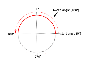
* `StartAngle`: Determines the angle from which the arc segment will start.
* `SweepAngle`: Specifies the length in degrees from the first to the second arc point. Positive angles are counter clockwise and negative angles clockwise.
The scheme below shows how `StartAngle` and `SweepAngle` are applied to the `ArcSegment`:
The following example shows a sample implementation of an `RadArcSegment` object.
Define the Path.
```XAML
```
Add the namespace:
```XAML
xmlns:telerik="http://schemas.telerik.com/2022/xaml/maui"
```
### RadLineSegment
The `RadLineSegment` creates a line between two points in a `RadPathFigure`. The starting point of the line is defined either by the previous segment's end point or by the `StartPoint` of the `PathFigure` object. The end point is defined by the `Point` property of the `LineSegment` object.
The thickness and the color of the line are determined by the `StrokeThickness` and `Stroke` properties of the Path object to which this line figure is added.
The following example shows how to create a line `PathFigure`.
Define the Path.
```XAML
```
Add the namespace:
```XAML
xmlns:telerik="http://schemas.telerik.com/2022/xaml/maui"
```
## Example
The following example shows how to create a more complex `RadPathGeometry` object and add a line with curved edges to its Figures collection.
**1.** First, define the `RadPath` figure:
```XAML
```
**2.** Add the namespace:
```XAML
xmlns:telerik="http://schemas.telerik.com/2022/xaml/maui"
```
**3.** Then, set its `Geometry` to have the following structure:
```C#
RadPathFigure customLine = new RadPathFigure();
customLine.StartPoint = new Point(0.8, 0.1);
customLine.Segments.Add(new RadLineSegment(new Point(0.1, 0.8)));
customLine.Segments.Add(new RadArcSegment() { Center = new Point(0.125, 0.825), StartAngle = 135, SweepAngle = 180, Size = new Size(0.070710678, 0.070710678) });
customLine.Segments.Add(new RadLineSegment(new Point(0.85, 0.15)));
customLine.Segments.Add(new RadArcSegment() { Center = new Point(0.825, 0.125), StartAngle = 315, SweepAngle = 180, Size = new Size(0.070710678, 0.070710678) });
RadPathGeometry geometry = new RadPathGeometry();
geometry.Figures.Add(customLine);
customLinePath.Geometry = geometry;
```
**4.** Add the namespace:
```C#
using Microsoft.Maui.Controls.Xaml;
using Microsoft.Maui.Graphics;
using System;
using Telerik.Maui.Controls;
using Telerik.Maui.Controls.Paths;
```
The following image shows the result after creating the three Paths:

## See Also
* [MultiPath](https://www.telerik.com/maui-ui/documentation/controls/path/multipath)
* [Styling](https://www.telerik.com/maui-ui/documentation/controls/path/styling)